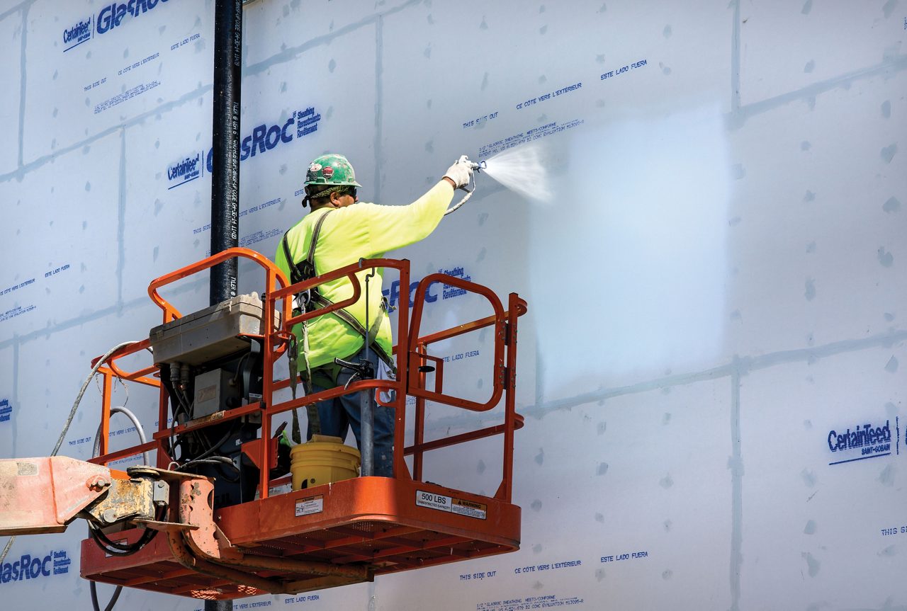
Protecting buildings from air, water, moisture and vapor with compatible barrier applications
Meet the installation and performance needs of modern building construction with liquid barriers that protect from air, water and vapor. Liquid barrier applications – such as acrylic emulsion polymers and water-based silicone technologies – can help you build an even better barrier and protect the building envelope. Whether meeting regulatory requirements for energy efficiency or enhancing weatherability, Dow barriers meet the need for high-performance building design. Key benefits of air, water and vapor barriers include:
- Airtight performance in a wide range of temperatures
- UV-resistant technology and advanced weatherproofing
- Long-lasting, primerless adhesion to challenging materials, including PVC and metals
- Durability
- Low-VOC formulation
- Bulk water resistance and covers a wide range of vapor permeabilities
Learn more about a compatible system that protects buildings from air, water and vapor.
Resources
Air Barrier Technical Drawings
- Masonry Parapet (103) - PDF or DWG
- Vertical Offset at Brick with CMU Wall (105) - PDF or DWG
- Masonry Wall at Penetration (106) - PDF or DWG
- Masonry Wall at Penetration (alternate 1) (106a) - PDF or DWG
- Masonry Wall at Penetration (alternate 2) (106b) - PDF or DWG
- Window/Curtain Wall Concrete Deck/Slab wit Waterproof Coating (301) - PDF or DWG
- Head: Curtainwall at Brick with CMU Wall (108a) - PDF or DWG
- Sill: Curtainwall at Brick with CMU Wall (109) - PDF or DWG
- Head: Storefront at Brick with CMU Wall (110) - PDF or DWG
- Sill: Storefront at Brick with CMU Wall (111) - PDF or DWG
- Projected Storefront at Brick with CMU Wall (112) - PDF or DWG
- Flange Window at Brick with CMU Wall (118) - PDF or DWG
- Projected Curtainwall at Brick with CMU Wall (113) - PDF or DWG
- Head: Flange Window at Brick with CMU Wall (116) - PDF or DWG
- Sill: Flange Window at Brick with CMU Wall (117) - PDF or DWG
- Window Opening Isometric Sequencing A- DOWSIL™ 778 Silicone Liquid Flashing (120) - PDF or DWG
- Window Opening Isometric Sequencing B - DOWSIL™ 778 Silicone Liquid Flashing (121) - PDF or DWG
- Window Opening Isometric Sequencing (122) - PDF or DWG
- Head Louver at Brick with CMU Wall (125) - PDF or DWG
- Sill: Louver at Brick with CMU Wall (126) - PDF or DWG
- Louver at Brick with CMU Wall (127) - PDF or DWG
- Head: Door at Brick with CMU Wall (128) - PDF or DWG
- Head: Hollow Metal Door at Brick with DMU Wall (129) - PDF or DWG
- Door at Brick with CMU Wall (130) - PDF or DWG
- Hollow Metal Door at Brick with CMU Wall (131) - PDF or DWG
- Storefront Head at Stucco on Masonry Wall (210) - PDF or DWG
- Storefront Sill at Stucco on Masonry Wall (211) - PDF or DWG
- Storefront Jamb at Stucco on Masonry Wall (212) - PDF or DWG
- Storefront Head at Stucco on Light Gage Stud Wall (220) - PDF or DWG
- Storefront Sill at Stucco on Light Gage Stud Wall (221) - PDF or DWG
- Storefront Jamb at Stucco on Light Gage Stud Wall (222) - PDF or DWG
- Storefront/Window/Curtain Wall Jamb at Direct Applied Stucco on Masonry/Concrete Wall (312) - PDF or DWG
- Storefront/Window/Curtain Wall Head at Direct Applied Stucco to Masonry/Concrete Wall (310) - PDF or DWG
- Storefront/Window/Curtain Wall Sill at Direct Applied Stucco on Masonry/Concrete Wall (311) - PDF or DWG
- Detail Section: Material Stud Wall to Concrete Base (01) - PDF or DWG
- Seismic Joint (32a) - PDF or DWG
- Seismic Joint at Parapet (33) - PDF or DWG
- Vent Shroud Flashing Isometric (51) - PDF or DWG
- Minor Penetration Flashing Isometric (52) - PDF or DWG
- Head: Curtainwall at Brick with CMU Wall (108) - PDF or DWG
- Stud Wall to Concrete Base A (01a) - PDF or DWG
- Stud Wall to Concrete Base B (01b) - PDF or DWG
- Vertical Expansion Joint End (Plan) (01c) - PDF or DWG
- Silicone Transition System (STS) at Parapet (03) - PDF or DWG
- DOWSIL™ DefendAir 200 with Self Adhered Membrane at Parapet (03a) - PDF or DWG
- Change in Wall Substrate (Plan) (04) - PDF or DWG
- Flanged Window Head – Metal Panel (16) - PDF or DWG
- Storefront Window Sill - DOWSIL™ 778 Silicone Liquid Flashing (17a) - PDF or DWG
- Flanged Window Jamb – Metal Panel (18) - PDF or DWG
- Hollow Metal Door Head (29) - PDF or DWG
- Door Jamb (30) - PDF or DWG
- Warn Soffit - Non-vented (34) - PDF or DWG
- Cold Soffit (34a) - PDF or DWG
- Base of Wall at Sloped Roof (35) - PDF or DWG
- Base Wall: Brick with CMU Wall (101a) - PDF or DWG
- Wall Penetration (Plan) (06) - PDF or DWG
- Wall Penetration (plan) Alternate (06a) - PDF or DWG
- Wall Penetration (Plan) Alternate 2 (06b) - PDF or DWG
- Curtain Wall Jamb at Flush Condition - STS Flashing (07) - PDF or DWG
- Curtain Wall Jamb at Flush Condition - DOWSIL™ DefendAir 200 Flashing (07a) - PDF or DWG
- Curtain Wall Head at Flush Condition - STS Flashing (08) - PDF or DWG
- Storefront Window Head (10) - PDF or DWG
- Storefront Window Sill - DOWSIL™ 778 Silicone Liquid Flashing (11a) - PDF or DWG
- Storefront Window Jamb (12) - PDF or DWG
- Electrical Box / Fixture - DOWSIL™ DefendAir 200 with Sealant - PDF or DWG
- Electrical Box / Fixture – Silicone Transition Sheet (STS) - PDF or DWG
- Ducting Penetration - PDF or DWG
- Walls at Floor Slab - PDF or DWG
- Vented Eaves - PDF or DWG
- Horizontal Projections – Knife Plate, After DOWSIL™ DefendAir 200 - PDF or DWG
- Change in Wall Substrate (Plan) Alternate (04a) - PDF or DWG
- Change in Wall Substrate (Plan) Alternate 2 (04b) - PDF or DWG
- Vertical Wall Offset (Plan) (05) - PDF or DWG
- Base of Wall at 2-ply Roofing Termination (36) - PDF or DWG
- Horizontal Projections – Knife Plate, Before DOWSIL™ DefendAir 200 (47a) - PDF or DWG
- Horizontal Projections – Concrete Embed Assembly (47b) - PDF or DWG
- Base Wall: Brick with CMU Wall (101b) - PDF or DWG
- Curtain Wall Head at Flush Condition (08a) - PDF or DWG
- Curtain Wall Sill at Flush Condition - STS Flashing (09) - PDF or DWG
- Curtain Wall Sill at Flush Condition - DOWSIL™ DefendAir 200 Flashing (09a) - PDF or DWG
- Curtain Wall Jamb at Outboard Condition – STS Flashing (13) - PDF or DWG
- Curtain Wall Head at Outboard Condition – STS Flashing (14) - PDF or DWG
- Curtain Wall Sill at Outboard Condition – STS Flashing (15) - PDF or DWG
- Deflection Joint Where Wall Passes in Front of Slab (20) - PDF or DWG
- Deflection Joint Where Wall Passes in Front of Slab – Alternate (20a) - PDF or DWG
- Deflection Joint Where Slab Interrupts Wall (Through Wall Flashing) (21)- PDF or DWG
- Louver Head (25) - PDF or DWG
- Louver Sill (26) - PDF or DWG
- Louver Jamb (27) - PDF or DWG
- Door Head (28) - PDF or DWG
- Knife Plate with Structural Steel (48) - PDF or DWG
- Detail Section: Slab Edge with Window Wall System (49a) - PDF or DWG
- Target Flashing at Knife Plate Isometric (50) - PDF or DWG
- Lapped DOWSIL™ DefendAir 200 at Knife Plate Isometric (50a) - PDF or DWG
- Detail Plan: Control Joint at Material Stud Wall (02) - PDF or DWG
- Alternate Detail Plan: Control Joint at Material Stud Wall (02a) - PDF or DWG
- Parapet - Adhered Roofing Installed Before DOWSIL™ DefendAir 200 (03c option 1) - PDF or DWG
- Parapet - Adhered Roofing Installed After DOWSIL™ DefendAir 200 (03c option 2) - PDF or DWG
- Parapet Sheet Roofing Membrane (non-adhered) Installed After DOWSIL™ DefendAir 200 (03c option 3) - PDF or DWG
- Hollow Metal Door Jamb (31) - PDF or DWG
- Seismic Joint (32) - PDF or DWG
- Electrical Box / Fixture – Foil-faced Self-Adhered Membrane (38) - PDF or DWG
Quick Links